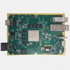
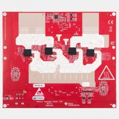
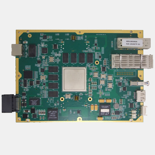
1. Overview This board is independently developed by our company, it is based on the MPSOC series SOC XCzu15EG-FFVB1156 architecture and equipped with two groups of 64-bit DDR4, each with a capacity of 32Gb and a maximum stable operation speed of 2400MT/s. There are also one 10G SFP+ optical fiber interface, one 40G QSFP optical fiber interface, one USB3.0 interface, one gigabit network interface and one DP interface. The board card has automatic power-on sequence and supports various start modes, such as Nor Flash start, EMMC start, SD card start and so on. The board card can dock with four AWR1243 MMW radar board MMWCas-RF-EVM of TI Company's . It can be used in high speed signal processing, vehicle radar signal processing and other fields. The design meets industrial requirements.
2 Hardware content The following is the hardware principle block diagram: Pin header 12-pin connector B Figure 3:ZU15EG Block diagram of board card principle Hardware interface content:
PS terminal mounts a cluster of DDR4, with data bit width 64-bit, capacity 32Gb, maximum stable operation at 2400MT/s;
PS terminal mounts two pieces of QSPI X4 NorFlash, each piece has a capacity of 512Mb and is used for system configuration program storage;
PS terminal mounts a piece of EMMC, with 64Gb capacity, can be used for system configuration program storage;
PS terminal plug-in SD card interface, support to search 8192 files maximum , can be used for system configuration program storage;
PS terminal external Display Port interface, support Display Port 1.2a protocol standard, only support external output;
PS terminal is connected with one way gigabit Ethernet interface, support 10/100/1000Mbps transmission rate;
PS terminal external one USB3.0 interface, the maximum rate can be up to 5 Gbps;
The board card is connected with one RS232 interface, which is rotated out by PS terminal UART0, and can be used for system debugging and status information printing;
The board card is connected with an RS485 interface, which is rotated out from THE PS terminal UART1 and can be used for system debugging and status information printing;
The board card is connected with two CAN interfaces, which are derived from the PS terminal;
PL terminal mounts a cluster of DDR4, data bit width 64-bit, capacity 32Gb, maximum stable operation at 2400MT/s;
PL terminal mounts a piece of DataFlash of SPI interface, with a capacity of 16Mb, which can be used to store system parameter information;
The QSFP interface on the external terminal of PL terminal supports the maximum data transmission rate of 40Gbps;
PL terminal is connected with one SFP+ interface, supports the highest data transmission rate of 10Gbps;
PL terminal is externally connected with two sets of 120-PIN high-speed connectors. Each set of connectors supports 12 pairs of LVDS and 52 channels of LVCMOS33;
The board card supports the mount of solid-state disk with m. 2 PCIe X4 interface;
The board card has multiple user-defined test IO pins;
The board card has a set of 4 users to customize the dial code switch;
Board card chips are all industrial grade chips;
Support 9V~36V voltage input range, with anti-back connection protection, over-voltage protection and other power protection functions;
3.Basic software content
PS terminal QSPI load test code;
PS terminal EMMC loading test code;
PS terminal SD card loading test code;
PS terminal DDR4 read and write test code;
PS terminal gigabit transceiver test code;
PS terminal RS232 interface read and write test code;
PS terminal RS485 interface to read and write test code;
PS terminal interface read and write test code;
PL terminal DDR4 read and write test code;
DataFlash of SPI interface on the PL terminal read and write test code
Pl-terminal QSFP interface ibert mode test code
Pl-terminal QSFP interface ibert mode test code
PL terminal M.2 SSD interface test code
Other GPIO signal connectivity test code
4.Platform software content 1)Based on the driver of TI Company, complete four pieces of TI company's cascade RF board (MMWCas-RF-EVM) of the ARM SDK software; 2)Complete the debugging of SPI and control interface development for cascade RF boards by PL terminal program 3)Completed the DATA receiving and frame grouping based on LVDS interface of four RF radar chips AWR2443 by PL terminal program; LVDS interface rate is not less than 450Mbps 4) Completed the PL terminal program to store the radar base-band data after the group frames into the DDR4 SDRAM of the PS terminal through AXI_HP bus; The amount of data cached per second does not exceed 480MB;
5) Completed the transfer of DDR4 SDRAM data in the form of FTP to PC to save as a file, through the Matlab program to verify the correctness of the data
6) Complete the program integration and debugging of the interfaces such as RS232, RS485, CAN and network port, and only test the data transmission function, not involving the business application data.
5 Physical Properties
5.1 Physical Characteristics Operating temperature: 0℃~+ 55℃ for commercial grade, -40℃~+85℃ for industrial grade Working humidity: 10% ~ 80% 5.2 Power Supply requirements Single power supply, maximum power consumption of the whole board: 30W Voltage: +12VDC± 10%@5a, 6 Application Areas High speed signal processing, vehicle radar signal processing, etc.